
Prior to the manufacturing of the speaker housing I decided to try and minimise the manufacturing time by cutting out the internal shell of the housing using the flatbed router. This meant that instead putting the internal cirlces to waste the flatbed router would simply cut the outline of the circles rather than boring the whole internal shell on the CNC. The would salvaged could be used elsewhere for future projects of a smaller scale or could be used to determine the finish without potentially jepardising the final outcome.
The video below depicts the Flatbed router in action. The router used a 6mm single flute high speed steel router bit for this project. The router leaves small tabs which must then be taken out using a chisel and some sand paper depending on the finish desired. The reason for leaving the tabs is, as the router makes its cut the internal material may tend to move and in some projects this may not be ideal as the internal cut may be the workpiece and not the waste.
Wooden dowels were used as a method of lining up each piece perfectly with the next. The reason for the use of dowels as also that while the CNC was in operation should the cutter cut through the dowel it would not harm the cutting tool (3.6mm Ballnose cutter). A 12mm MDF base was also made for each section prior to CNCing as a clamping would be required in Unimatic eduCAM (CNC) and should a base not be provided the CNC would simply cut through the clamps.
Tightbond glue was used as the adhesive before both surfaces came into contact and was clamped using the bench vice and three bar clamps. The piece was then left overnight to allow for a stronger hold. A maximum of just two pieces were glued together at any one vice and at any one time.

Once the pieces had been glued together they were clamped into the CNC machine and the programme was run. The videos below depict the CNC cutting out the files drawn.
Below is the front face of the larger base speaker which had just been machined which rests beside the proposed front face of the small speaker which had yet to be machined. The finish provided by the CNC was quite good while some sanding would be required later in the project.
Both speaker housings required six pieces of 20mm oak glued together however due to the cutter constraints the tool can only reach a depth of 45mm. Hence six pieces in total required CNCing.

Once fronts and mid sections of the speakers had been machined it was possible to being glueing these parts together while the backs were being machined. Again Tightbond was used as the adhesive as the pieces where clamped together using the bench vice and two bar clamps.

The pieces had been left overnight to dry and by the next day the back pieces had been machined. These however would not be glued just yet as some milling had been required to provide the base for the speaker and clamping a sphere would not only be somewhat difficult to do correctly but would also be very dangerous. The Milling machine could destroy the piece had it caught on it and pulled it out of the vice and also may have thrown it across the workshop.

Using two flat surfaces and clamping those in the vice was far more rewarding and provided strong support to the workpiece while it was being milled and drilled and it also made a much safer working enviroment.
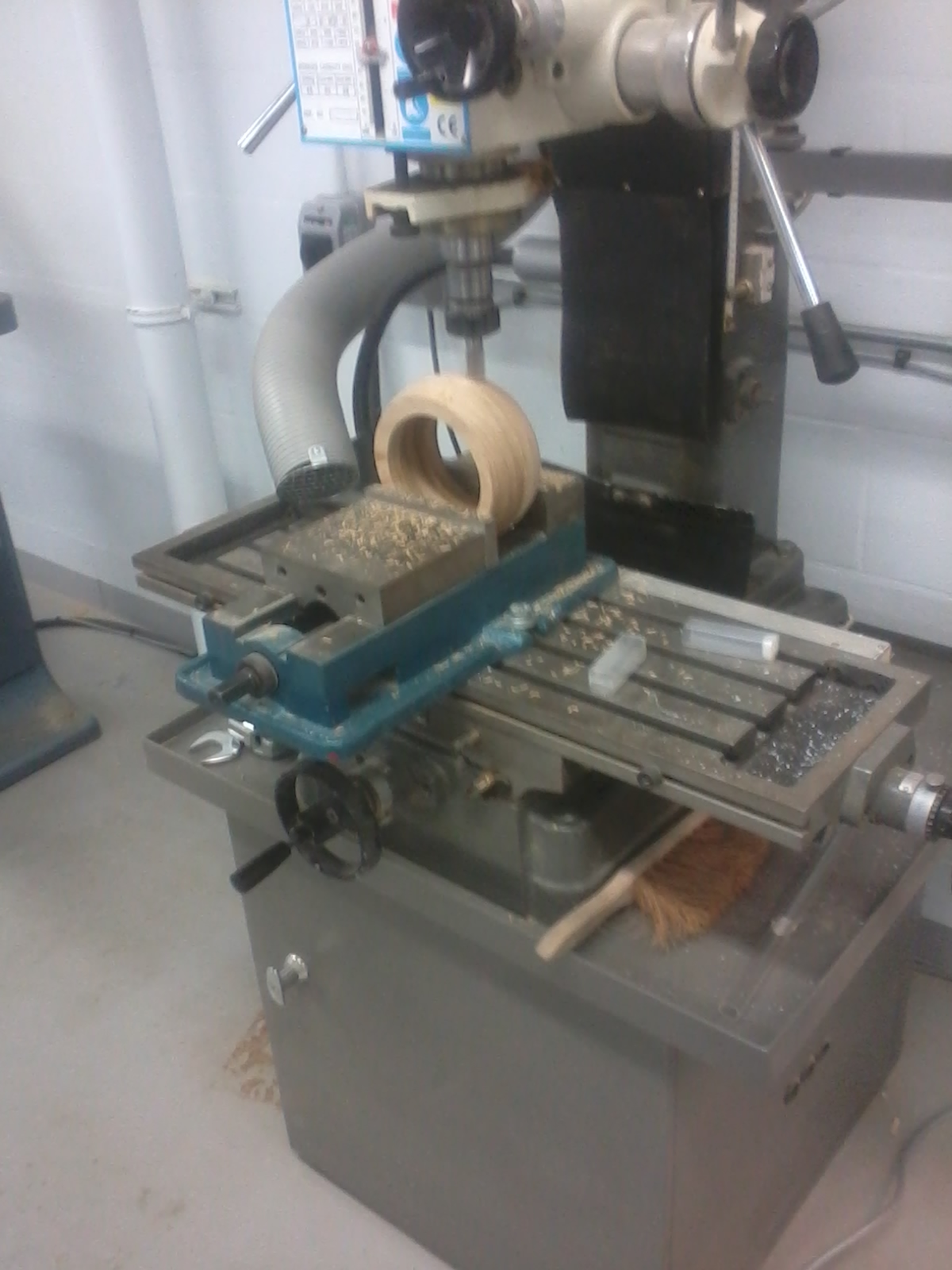
A 20mm slot mill bit was used for milling a flat base of 70mm diameter.


The centre of the base was found and transfered to the top of the workpiece using a sqaure. This would provide an accurate reading as the the highest point of the speaker housing. Once found it was then clamped again in the vice and drilled using the same 20mm slot milling bit. A 20mm hole was also drilled in the centre of the small speaker housing.

A 20mm hollow accrylic dowel was then used to determine the fit of the dowel between both the top and bottom speaker housing. The base was also tested to see if it would provide surface area for the speaker to stand comfortably.

Elastic bands were used to hold the backs of the speakers and the speaker finials in place and again the base was tested to determine if there was enough stability in the base to hold the extra weight on the back.

Glueing of the backs onto the speaker could now be done and again Tightbond adhesive was used and the top speaker was clamped using the bench vice only as was the vice was able to clamp a sufficient surface area. The larger bottom speaker was clmaped using the bench vice and a bar clamp.


Again the stability of the speaker was tested and as it had passed the test it meant that the speakers had reached a stage of filing and sanding. The picture below portrays the contrast between the finish of the large speaker housing once filing had been complete and the finish of the smaller speaker housing prior to filing.

The image below portrays the finish of the speakers once filing and sanding had been complete.

No comments:
Post a Comment